In previous lectures we have seen how it is possible to build circuits to do arithmetic (at least addition) using the the AND, OR
and NOT gates. It is instructive to look a bit further to see how we can cleverly combine some
of these elements to obtain new functions. For example, a slight modification of the ADD device
which we designed can give a SUBTRACT device. This is possible by taking advantage of the
simple mathematical fact,
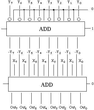
In other words, we can subtract Y from X with our ADD device as long as we can also change the sign of a number. Recall that in 2's-complement the sign of a number is reversed by complementing all of the bits and then adding 1 to the result. Thus, the following circuit will transform Y to -Y. Recall that the open circles representX - Y = X + (-Y)
NOT gates. Also, notice the carry-in value of 1 which will accomplish the desired goal of adding 1 to the representation of
Y after all the bits have been reversed.
We can then subtract by connecting the inputs from X and the outputs from the -Y to a second adder.
Actually, it's even simpler than that because the second
ADD
device is unnecessary. Actually, we need only apply the NOT operation to the normal
inputs from Y, then carry in a 1, in this way only one ADD is required.
This can be written in shorthand as a block diagram,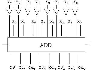
where X (8) is a reminder that 8 input wires are needed for the X values. Likewise, Y (8) and X-Y (8) remind us that there are 8 wires for the Y input and 8 output wires for the result of the subtraction. The details of construction of MUL and DIV circuits are beyond the scope of this course. The reader may wish to consult a reference on computer architecture to explore these topics.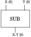
From Arithmetic to Logic
Now that we have discussed the basics of arithmetic via gate circuitry, we can consider the other function of the ALU, Logic. It is possible to design circuits to compute logical (true/false, 1/0) results.
Consider, for example, the two logical comparisons of the PIPPIN machine. Instructions are found for CPL and CPZ. Each of these instructions look at 8 bits of data and return a one bit result: 1 for true, 0 for false. In fact, these instructions return 8 bit results because the PIPPIN machine (like most real computers) doesn't work with one bit at a time, rather the machine works with 1 byte. The design of a CPL (compare for less-than-zero) circuit is terribly simple in a machine that uses a 2's complement representation. Recall that a negative number is distinguished by its first (most significant) bit being set to 1. Thus, the CPL function can be designed as follows.
It is only somewhat more difficult to implement the CPZ (compare to zero) circuit. An eight-input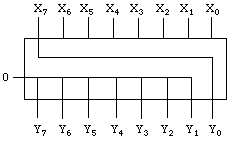
OR
gate does the trick. This is a circuit which will yield a 1 if at least one of its inputs is a 1. Thus, it will
yield a 0 only when all inputs are 0. By connecting the output of this circuit to a NOT gate, we have the
CPZ function.
More intricate circuits are used in today's computers. For example, a "magnitude comparator" is a circuit which is used to compare two inputs, say A and B, and then determine which of the following is true: A < B, A = B, A > B. For example, a two bit magnitude comparator would be designed as follows.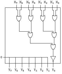
Let the two bits of A be called A1 and A0.
Likewise, B is B1 and B0.

if A1 < B1 or (A0 < B0 and A1 = B1)
    A < B
else
    if A1 = B1 and A0 = B0
        A = B
    else
        A > B
< operation is easy to construct for a single bit comparison:
Which corresponds to the logical operation
A'B. Likewise, A = B corresponds to the XOR gate followed by
a NOT gate, called exclusive-NOR,
The design of such a circuit is fairly simple from a logical standpoint, but it can be quite daunting to examine the logic diagram to understand the circuit's function. Interested students may wish to study the product data sheet for the Motorola 4-bit magnitude comparator.
Putting it all together
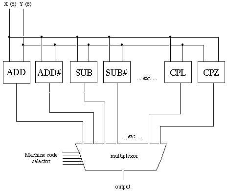
Now that we have the basic construction of each of the operations of our computer, we can put them all together into the ALU. The increase the speed of processing, the ALU actually computes all possible results for every input. That is, as soon as two 8-bit values are sent to the ALU, the values are added, subtracted, multiplied, divided, compared, all at the same time. This parallel approach sounds like more work, but it's really more efficient than taking the time to decide which operation to perform, then performing it. This is very easy to do as shown below.
The main problem now is to determine how to pick which of the many answers we're supposed to use after the computation. In order to do this, we need a circuit which can take many inputs and select only one of them as the output. Such a circuit is called a multiplexor. Multiplexors can handle any number of inputs and they always yield only one output. The most basic design is a 2-to-1 multiplexor (2x1 mux) whose circuit is shown below.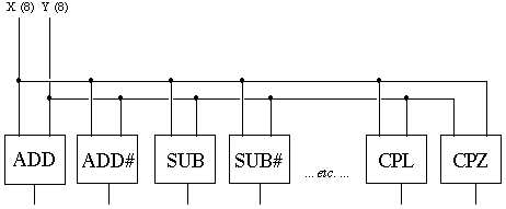
Notice that the circuit above uses an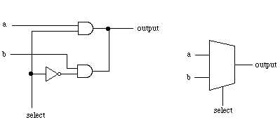
AND gate to select the output. If the select wire is on, then
the upper AND will pass a 0 if the top input is 0, otherwise it will pass a 1 if the top input is 1. In other words,
it passes the value of the top input. On the other hand, when the select wire is off, the inverter on the bottom
AND will activate that gate to pass the value of the lower input. In other words, the logic table
is,
Now suppose we use three 2x1 mux devices and connect them as follows,
with the logic table,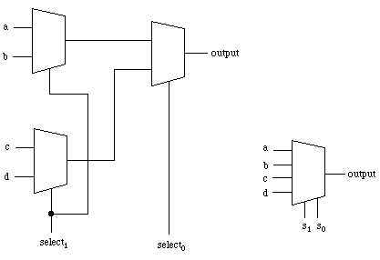
But why stop there? We could connect two of these 4x1 mux devices to another 2x1 mux to give an 8x1 mux,
and so on and so on, until we have any number of inputs, but still just one output line. This is the secret to the ALU's operation. The machine instructions such as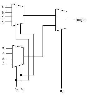
ADD, ADD#,
SUB, MUL, CPL, CPZ, etc. each have their
own unique pattern of 0's and 1's. Thus, the ALU gives all possible outputs to the the multiplexor
which uses the machine code to select the proper outcome. For example, PIPPIN only has 20 possible
instructions, four of which are for control (JMP, JMZ, NOP, HLT)
which do not require data from the ALU. For example, the following codes are used in PIPPIN:
These codes select the output from the ALU organized as,